Hello-
I’m making a MIDI device based on the Raspberry Pi Zero W. I have gotten MIDI input working on my project, it’s output that’s stumping me. I think it’s a hardware problem.
I have a logic level shifter between my 3.3v GPIO pins and the breakout board, using a 5v reference level from one of the 5v GPIO power pins going to the HV pad.
I’m absolutely new to PCB electronics but I have a suspicion that one of the DIN connectors that came with my MIDI breakout board could be defective and I was wondering if you could help me confirm whether that’s true. Basically my question boils down to: is it possible to test continuity between the Xmit pad and the Out connector’s signal pin using a multimeter?
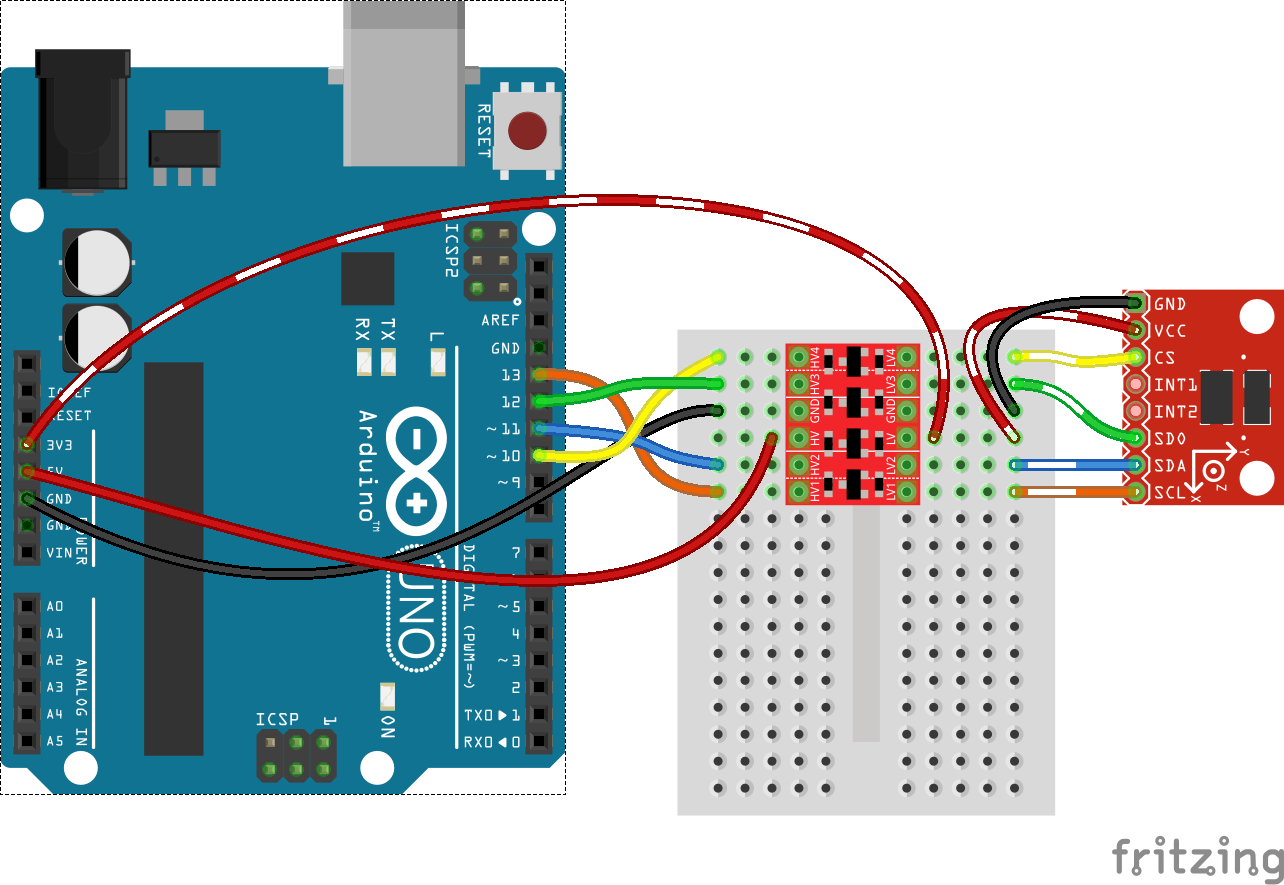
Besides that I would guess that something is wrong with my use of the converter, but I was very careful to hook up everything with the help of this diagram: https://cdn.sparkfun.com/assets/learn_tutorials/1/4/7/spi-example_bb-02.png (I know that is an Arduino board but I think the only difference when it comes to this is the layout of the pins.)
.